
BO-Solutions combines a CAD-CAM environment, 3D metrology, and a climate-controlled measuring chamber to translate any design into a manufacturable precision part – accurate to within 5 microns.
From 2D sketch to validated end product: digitally modeled in our CAD-CAM environment, smartly programmed, and measured to within 5 microns in our temperature- and humidity-controlled measurement chamber.
Since 1988, customers have entrusted us with their precision measurements.
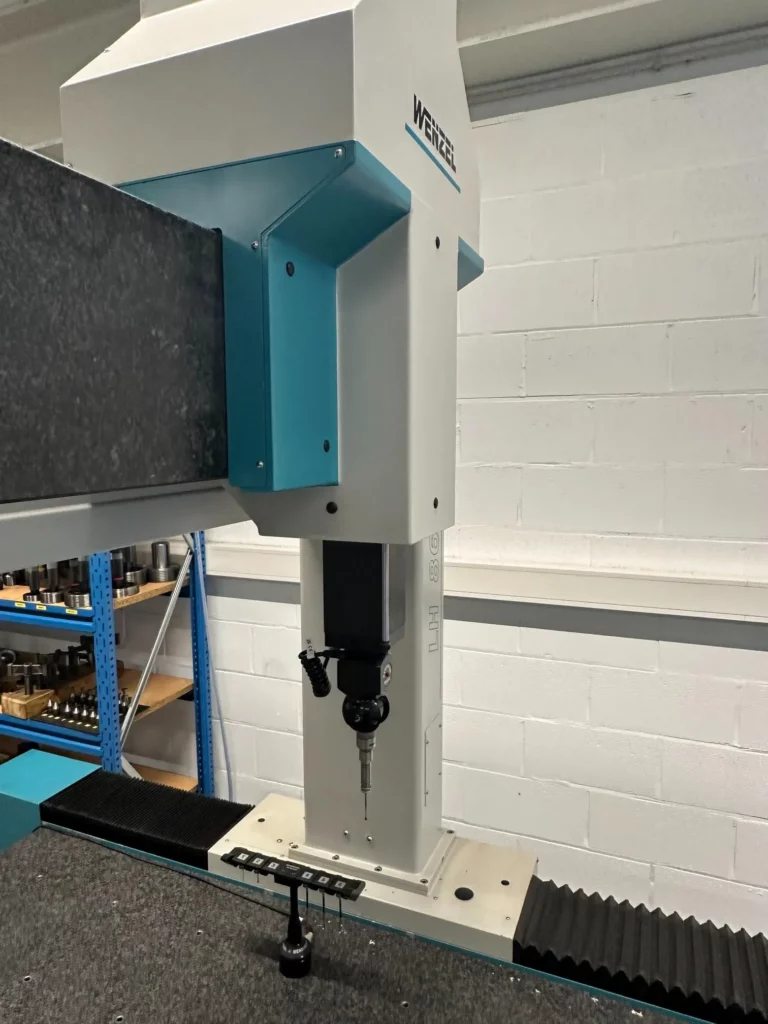
With CAD-CAM software and 3D measurement technology, we bring engineering, production, and inspection together. Your design is manufactured and inspected to within 5 micrometers.
What we do:
This creates a direct line from CAD to CAM, with a zero margin of error and fast startup at the machine.
Our 3D measuring machines inspect parts down to the micron, ensuring your product is exactly within tolerance.
Our 3D measurements include:
Result: objective, traceable quality data. Precision as it should be.

Ideal for remanufacturing, modifications, and precision work
Our CAD-CAM 3D measurements are suitable if you:
In this way, every step is substantiated: from digital model to controlled, perfect end product.
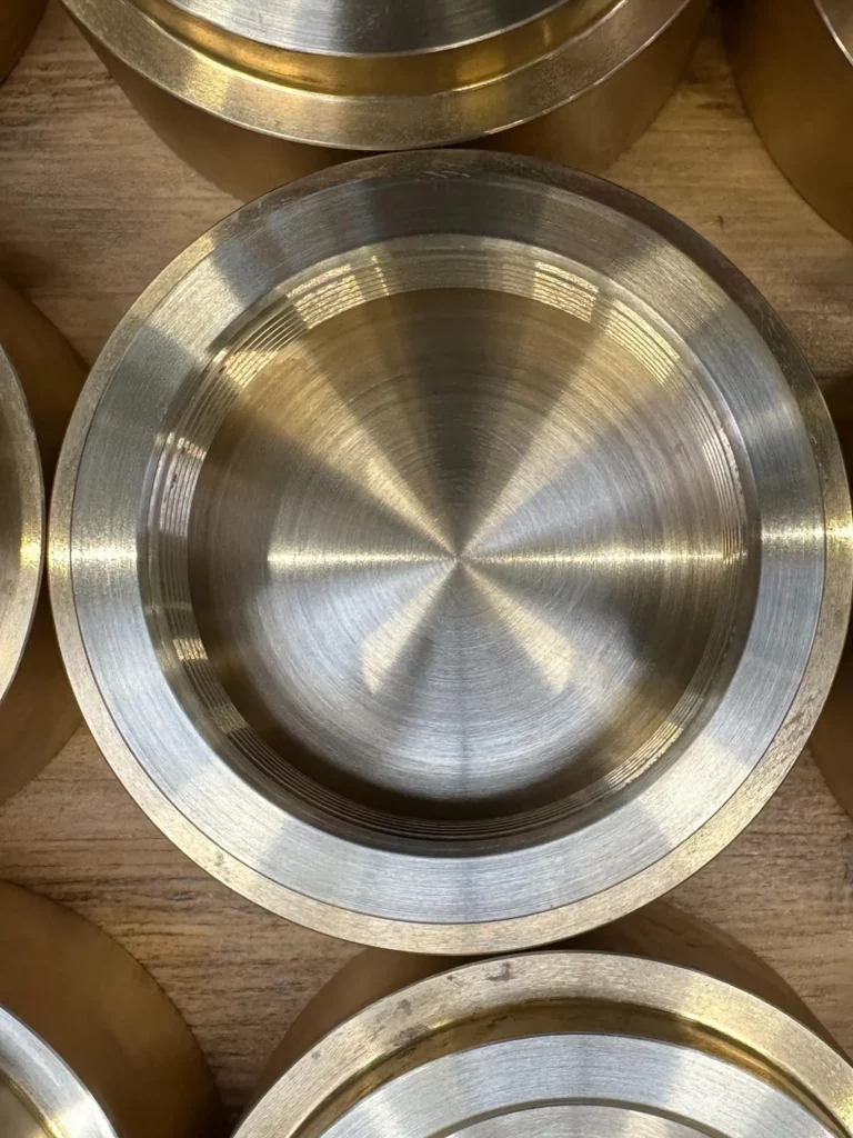
Choosing CAD-CAM 3D measurements at BO-Solutions means:
Send us your project information via the contact form.
We translate your drawing, 3D model, or part via CAD/CAM into a manufacturable and controlled precision part.
Direct contact: +32 51 24 89 32 // info@bo-solutions.be
CAD (Computer-Aided Design) is about designing and modeling products in 2D or 3D.
CAM (Computer-Aided Manufacturing) uses those CAD models to generate CNC programs and machining strategies for machines. At BO-Solutions , CAD and CAM merge seamlessly, ensuring that design and production align perfectly.
CAD in 3D modeling means that a part is built entirely in three dimensions in software. This makes dimensions, shapes, fit, tolerances, and machining processes immediately visible. This is the basis for CAM programming, simulations, and 3D measurements.
A CAD-CAM programmer translates designs and 3D models into practical CNC programs. He/she selects tools, machining strategies, speeds, and fixtures, and ensures that the part can be produced manufacturably, efficiently, and within tolerance.
CAD stands for Computer-Aided Design. It is the collective name for software used to create, modify, and manage technical drawings and 3D models.
There are various types of CAD systems, including:
At BO-Solutions , we work with 3D CAD (Inventor) as the basis for CAM programming and 3D measurements.